Monday, May 31, 2010
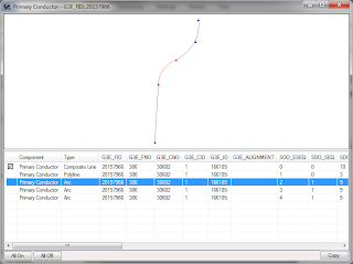
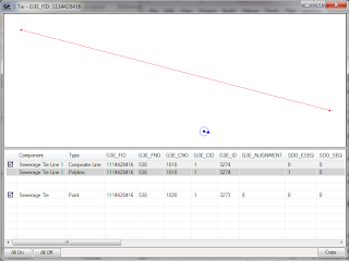
Geometry Info in the GT/Metadata Explorer
GT/Metadata Explorer version 1.0.0.34 is Available
Wednesday, May 19, 2010
Coordinate Factors – What are They? How Do You Set Them?
The Coordinate Factors are 6 numeric values defined in the [General Info] section of the .GTM file using the following entries:
- CoordinateFactor1X
- CoordinateFactor1Y
- CoordinateFactor2X
- CoordinateFactor2Y
- CoordinateFactor3X
- CoordinateFactor3Y
The Coordinate Factor values are used to convert Real-World Coordinates (sometimes referred to as Computed Coordinates) to GTViewer’s Internal Coordinates (sometimes referred to as System Coordinates) and vice versa. Real-World Coordinates are coordinates in the data’s native coordinate system, such as State Plane, Latitude/Longitude, UTM, etc. These values are usually double precision floating point numbers. GTViewer’s internal coordinates are stored such that they require less storage space in the graphic files (.gtg) and the spatial index files (.gtn). Instead of storing coordinate values as double precision floating point values (which are 8 bytes each), they are instead stored as an unsigned 32 bit integers (which are 4 bytes each). This change of type brings an immediate 50% saving in the data size; however, the internal coordinate values no longer reflect their real-world positions. To get around this problem, the Coordinate Factors provide the necessary information to restore the internal coordinates to real-world coordinates.
There are really only two places where the effects of the Coordinate Factor values can be seen in GTViewer: the Coordinate Readout on the status bar and the GPS Functionality. Without the Coordinate Factors, the coordinate readout on the status bar would show GTViewer’s internal coordinate values which are likely meaningless to the users. With properly configured Coordinate Factors, the readout will show Real-World coordinates. The GPS functionality must be able to convert the Latitude/Longitude coordinate it gets from the GPS Receiver to GTViewer’s internals coordinates so that the GPS Indicator can be drawn at the right position. GTViewer’s coordinate transformation routines will convert points from Latitude/Longitude to one of the many Real-World coordinate projection systems it supports, then the Coordinate Factors are used to take the real-world coordinates to GTViewer’s internal coordinates system.
To understand how the Coordinate Factors work, there is some simple math involved. The Coordinate Factors are the variables used in the following formulas to convert Real-World coordinates to GTViewer’s internal coordinates:
GTViewerX = ( RealWorldX + CoordinateFactor1X) * CoordinateFactor2X + CoordinateFactor3X
GTViewerY = ( RealWorldY + CoordinateFactor1Y) * CoordinateFactor2Y + CoordinateFactor3Y
To convert GTViewer internal coordinates back to Real-World coordinates, the above formulas are simply rewritten as:
RealWorldX = ( GTViewerX – CoordinateFactor3X) / CoordinateFactor2X – CoordinateFactor1X
RealWorldY = ( GTViewerY – CoordinateFactor3Y) / CoordinateFactor2Y – CoordinateFactor1Y
It may not be obvious how the Coordinate Factors should be set just by looking at the formulas above, but the goal is simple. The coordinate factors are set so that any point in the dataset (Real-World coordinates) will map to a point whose X and Y are both unsigned (positive) 32 bit integer whose range is 0 to 4,294,967,296. There are many ways to figure out what the Coordinate Factors should be to meet this goal, and I will go through the simplest approaches below.
Think of GTViewer’s coordinate space as a window whose lower left is always (0,0) and whose upper right is always (4294967269,429967296). This coordinate space is very large even if it is somewhat smaller that a double precision floating point coordinate space. To map the real-world coordinate values into this window, we simply adjust the coordinate factors so that the real-world points are properly scaled and shifted.
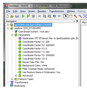
The Coordinate Factor X2 and Y2 are the multipliers (which will scale the data), so they are used to get the precision you need for the GTViewer data. With Latitude/Longitude data, you need around 6 decimal places, so you can set the X2 and Y2 to 1,000,000. Then when the Real-World X or Y is multiplied by the X2 or Y2 Coordinate Factors, you will get 6 of the digits after the decimal place as part of the number. If your data is in Feet or Meters, then can you set the X2 and Y2 to 100 or 1000, which means that you will get precision to 100th or 1000th of a foot or meter.
Latitude/Longitude Example:
Real-World X=-86.4664839 (Longitude)
Real-World Y=34.6550175 (Latitude)
To preserve 6 decimal places, we set the X2 and Y2 Coordinate Factors to 1,000,000.
GTViewerX = -86.4664839 * 1000000 = -86466484
GTViewerY = 34.6550175 * 1000000 = 346550175
The Multipliers preserve the precision when the values are converted; however, in the example above, the GTViewerX value is negative. The X1/Y1 and the X3/Y3 Coordinate Factors are the Shift values and come in here to move the data back into the positive space. It is also possible that the GTViewer coordinate values may exceed the 4,294,967,296 maximum after the Multipliers are applied, so the Shift values can also be used to move the data back down into the desired coordinate space.
The difference between the X1/Y1 and the X3/Y3 Coordinate Factors is that one is applied before the Multipliers and the other is applied after the Multipliers. This difference also means that the X1/Y1 Coordinates factors will be in Real-World units, while the X3/Y3 Coordinate Factors are in GTViewer’s System units. It generally doesn’t matter if you use the X1/Y1 or the X3/Y3, and you would rarely use both at the same time.
For the Latitude/Longitude example it is more straight forward to use the X1/Y1 since they are in real-world coordinate units (degrees). We know that Latitude has a range of -90 to +90 and Longitude has a range of -180 to +180. In both cases, there can be negative values, and the X1 and Y1 Coordinate Factors need to account for possible negative values. In a meticulous world, we would simply say that X1=90 and Y1=180, and we would be guaranteed to have positive values before the multipliers are applied and the resulting values would always be positive. In practice, it is good to have a little buffer around the data and to prevent confusion on which Coordinate Factors needs to be 90 and which one needs to be 180, I use 200 for both X1 and Y1. The X3 and Y3 Coordinate factors are not needed and can be set to 0. So, for Latitude and Longitude data, the formulas look like this:
GTViewerX = ( RealWorldX + CoordinateFactor1X) * CoordinateFactor2X + CoordinateFactor3X
GTViewerX = ( -86.4664839 + 200) * 1000000 + 0
GTViewerX = 199999914
GTViewerY = ( RealWorldY + CoordinateFactor1Y) * CoordinateFactor2Y + CoordinateFactor3Y
GTViewerY = (34.6550175 + 200) * 1000000 + 0
GTViewerY = 234655018
The Converted Coordinates meet the criteria of being between 0 and 4294967296 and we preserve 6 decimal places of precision from the original values. It is a good idea to test the extreme values (lat: -90, long:-180) to ( lat:90 to lon: 190) through the formulas to make sure they still fit in the GTViewer coordinate space, but for brevity I will omit that from this posting.
Since most user data is probably in a State Plane coordinate space or similar, I will go through the process for determining the Coordinate Factors in this case as well. The Real-World Coordinates are generally in Feet or Meters and we typically do not need more than 2 or 3 decimal places for precision, so the X2 and Y2 Coordinate factors can be set to 100 or 1000. If your data range is positive, you may not need an X1/Y2 or X3/Y3 to shift the data. We can mathematically compute the perfect Multipliers and Shift values to maximize the amount of the GTViewer coordinate space, but this extra work usually causes problems in the long run. Just make sure the values are positive and there is a little buffer around the data. It is a good idea to know the approximate range of your dataset in Real-World coordinates. If you have any negative values, then you will have to shift the data into the positive space by setting X1/Y1 to at least the absolute values of the smallest negative value (plus a little more for a buffer). If your highest values after the Multiplies are applied are greater than the 4,294,967,296, then you can set your X1/Y1 or X3/Y3 values to a negative value to brings the values under the limit. This description is vaguer than my description for Latitude/Longitude data, but there are simple tests to see if your Coordinate Factors are good. If you look at the data in GTViewer and the data “wraps” around to the other side, then the data needs to be shifted.
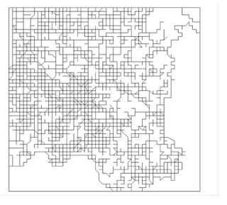
The first example below shows the data with the Coordinate Factors properly set:

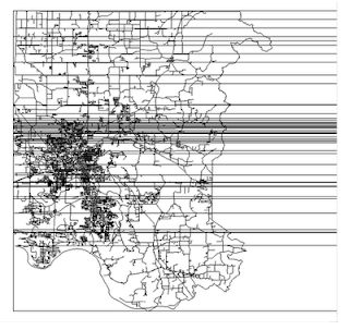
The following example shows data where the coordinates have negative values and the data is wrapping around from the left to the other side of the design plane. The data needs to be shifted to the right, so the X1/Y1 need to be set to higher values.
When FME gets ready to write the GTViewer data as output, it has Real-World Coordinates (in the Coordinate System set for the destination). The Coordinate Factors are then applied to the Real-World coordinates to get GTViewer internal coordinates. Many users have asked why you have to set these values with FME. It is certainly possible get the range of the data and use this information to compute good values for the Coordinate Factors. However, there are many draw backs to making this part automatic:
- Setting the coordinate factors is a one-time thing, so expending a lot of computation effort to set them each time the data is converted is not practical.
- All of the data would have to be processed to get the range, then processed again for the conversion.
- Data is notoriously bad. One stray feature would corrupt the range and create a bad set of Coordinate Factors.
- You don’t want the Coordinate Factors to change from one run to the next. Adding new data to a dataset could change the range which would change the Coordinate Factors. Then data from previous runs and redlines would not overlay with the current data.
Using Coordinate Factors with Microstation/IGDS Data
Working with Microstation/IGDS data has a few interesting quirks that can be taken advantage of if you know what to do. A DGN file is also bound by a 32 bit integer Design Plane. However, the Global Origin concept is used to specify where in the Design plane (0,0) occurs allowing negative values to be used. By default, the global origin is in the middle (2147483648,2147483648) which allows the design plane to have a range of something like (-2147483648,-2147483648) to (2147483648,2147483648). The X3/Y3 Coordinate Factors can be set to 2147483648 to compensate for the origin. If the Global Origin is set to a specific location, then Coordinate Factors must reflect this configuration. GTData contains a utility called GTGetOffset that will attempt to get global origin info as well as the UORs per master unit from a DGN File and generate the CoordinateFactor entries for the .GTM file. While this utility is not always correct (depending on the configuration of the data), it can be very useful.
Thursday, May 13, 2010
PGTV .NET Control version 9.0.0.3 is Available

GTV .NET Control Version 9.0.0.8 is Available

The GTViewer .NET Control for Windows version 9.0.0.8 is Available.


